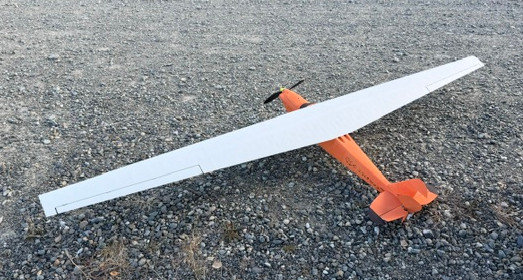
Model B equipped with a glider wing.
I recently tried my hand at designing and building a 3D-printed glider wing for one of my RC planes. Mechanically, the wing turned out great, unfortunately a test flight revealed it did not function well with the rest of the plane. However, I learned a lot throughout the process and it was definitely time well spent.
A bit of a backstory, over the summer, my son and I built several 3D-printed planes together. Two of which are still airworthy! What really surprised me about them was the specific way they are designed and printed; they uses a printing method called vase mode or spiral mode. It was so interesting that I wanted to try doing something similar myself.
Designing a whole plane seemed like too big of a step, so I decided to create a replacement wing for the Eclipson Model B, a Cub-style bush plane with a removable wing that attaches with a couple screws. It seemed like a good candidate since a replacement wing would only need a set of screw holes in the correct location to fit on the plane. I'm also interested in long-range flying and wanted to explore that space as well.
This ultimately guided my thought process when choosing a design for the wing. Obviously a bush plane is never going to be a great long-range machine, but I thought it could be a platform to at least experiment with some ideas. I'd like to say that every design choice was carefully calculated but the reality was, I kind of just winged it.
Wing Shape
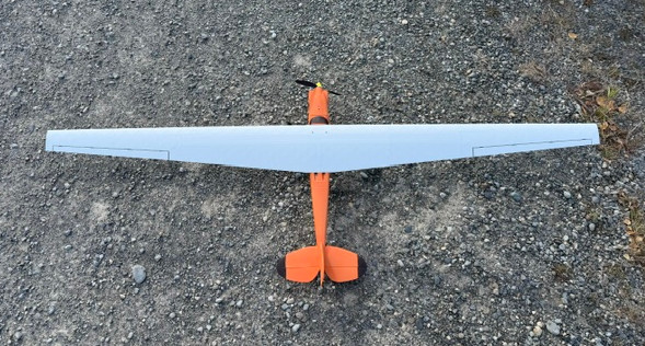
Glider wing planform profile.
Glider wings typically have a long narrow shape because they are more efficient at producing lift while reducing drag. So, with that in mind, the new wing has a 2 meter wingspan (quite the jump from the 1.1 meter wingspan of the original wing) and a heavy taper. The root chord is 180mm at the fuselage, almost the same as the original wing, and tapers entirely along the trailing edge to only 80mm at the wing tips. Tapering along the trailing edge was done mostly to make construction slightly simpler by aligning the spars and servo conduits along the leading edge.
As for the airfoil, the popular Clark Y was the choice here. Clark Y is a go-to airfoil shape for model planes, in large part, because the underside is flat which makes construction easier for wooden models. That doesn't really matter for 3D-printing, but I figured it would at least be a benchmark to compare any other future wing designs or airfoils to.
Modelling the Wing
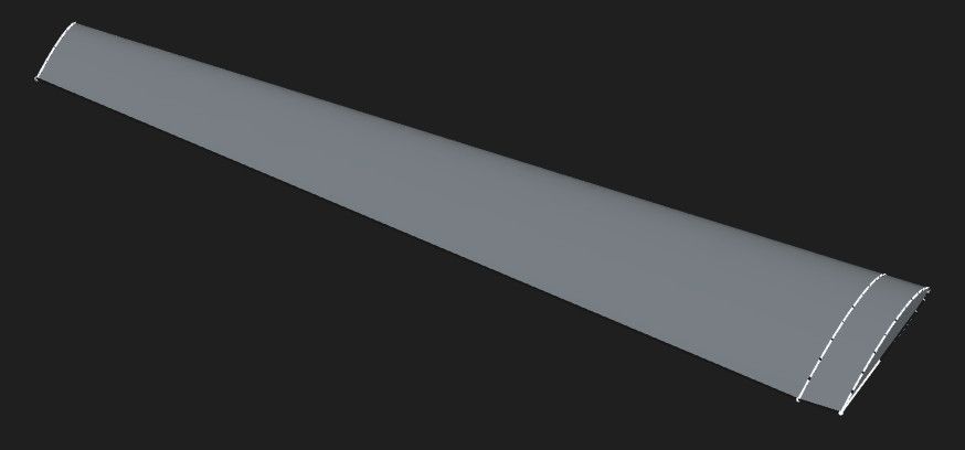
Basic 3D shape of glider wing in FreeCAD.
Modelling the wing in FreeCAD had two distinct steps. First importing the airfoil shape and extruding the overall wing profile. Then preparing the wing for 3D printing, which is where the bulk of the effort was.
Getting the airfoil into FreeCAD was not too bad. Airfoil Tools allows exporting the airfoil profile, then a popular FreeCAD macro, Airfoil Import & Scale can turn the profile into a sketch. From there, it's just a matter of copying and scaling the airfoil profile along the length of the wing, then lofting between them.
For a straight tapered wing, I lined up the front-most part of each airfoil sketch before lofting the final shape.
I've come to learn that something called washout is also usually recommended for wings like this. Washout is a small 1-3 degree reduction in the angle of attack at the wing tip compared to the root of the wing. With the wing tip chord being smaller than the root, it is prone to stalling and losing lift before the larger sections of the wing. Less angle of attack can delay the stall until after the root of the wing, producing a more controllable stall behavior. Something to keep in mind for a version 2.
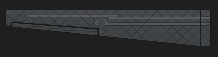
Internal structure of the glider wing showing: spar holes, servo conduit, and internal supports.
With the the 3D body of the wing constructed, next came the much more laborious task of preparing it for printing and assembly.
A wing needs control surfaces like ailerons, so those needed to be cutout from the wing body. And to move the ailerons, I cut a mounting hole and a conduit through the wing body for the cabling.
For a wing of this size, more support than just the flimsy lightweight 3D printer filament is also needed. So, I cut spar holes into the model that carbon fiber tubes could be inserted into for rigidity. A long 1 meter carbon fiber tube connects both halves of the wing together, and smaller 450mm length tubes add rigidity further down the wing.
Finally, the wing needed an internal structure to support the outer skin and also to add additional rigidity. One way to do this is to just use a low percent infill setting in the slicer when printing. However, I was really enamored by Eclipson's models and how they can be entirely printed in vase mode and wanted to try making this wing compatible with that printing method.
Vase mode printing uses one continuous extrusion of filament to print an object. It will also only print the outer surface of an objects, so models with complex shapes have to be carefully designed so that the outer surface of the object contains all the elements of the final design.
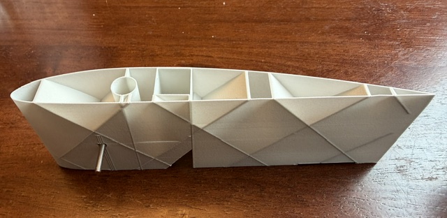
A test-print of the wing showing the internal structure. Printed using spiral vase mode.
Essentially what is done for a wing, within the model itself, very thin slices are cut into it from the underside. These little slices go almost to the topside but stop just shy of it, maybe 0.4mm. This creates little pockets the go into the model but that don't create any holes through it. Topologically, the wing ends up being kind of cylinder that folds in on itself. The 3D printer will follow all the walls of these cavities and never have to lift the print head up until the print is done.
I think the best way to see this is in the following image from the slicer. Each supporting element is just a small sliver cut out of the main wing body.
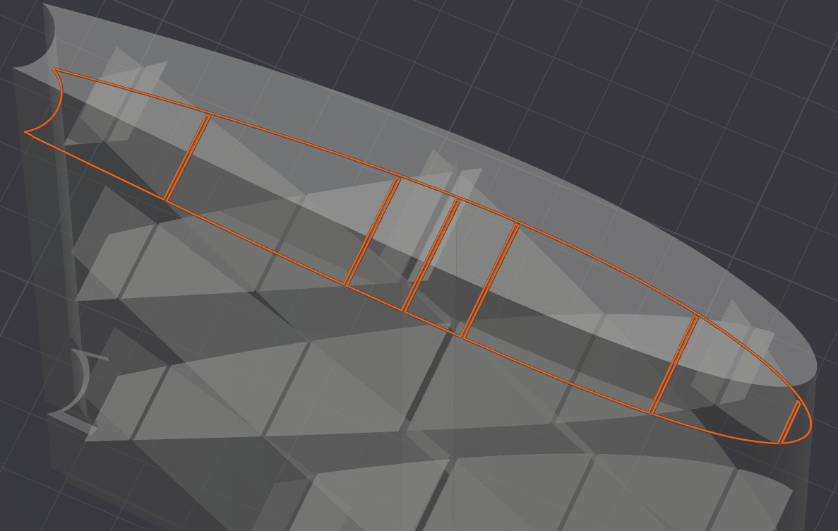
Screenshot from Bambu Studio showing the toolhead path for a single layer of a wing being printed in spiral vase mode.
This whole process is especially advantageous because the light-weight 3D printing filament, used for model planes, foams as it gets heated in the nozzle. If the print head lifts, it continues to foam and gets everywhere and creates stringing. If the printer is continuously laying down filament, there is no stringing.
Trying to get a vase-mode compatible wing took a ton of time messing around in FreeCAD, to the point where I'm not sure if the juice is worth the squeeze. At least for a prototype, or proof-of-concept, I think it's too much effort. It is however, a super cool way to make 3D printed model aircraft.
Test Flight
We were quickly running out of warm weather up here in the north, but luckily there was a day with decent skies and low wind for a maiden flight using the new wing.
The takeoff went very well, but once in the air things started to go poorly. The whole plane would yaw uncontrollably, especially when trying to do any roll maneuvers. It was very nerve-wracking and I'm very happy I had a gyro on board to help stabilize the plane. Otherwise, I'm sure it would have ended up in the woods somewhere.
After a bit of reading, and feedback from some folks, the reason for this is likely that the vertical stabilizer on the Model B is just too small to counteract the extra yawing forces that a much wider wing was producing.
Thankfully the plane made it back mostly in one piece. A little damage to the tail section, but the wing and everything else seemed to make it out unscathed.
Since the wing is still in one piece, I would really like to try designing a fuselage for it over the winter. Something more appropriate for a 2 meter-wide glider wing.
I've also uploaded STEP files and assembly instructions to my GitHub for those interested.
Thanks for reading!