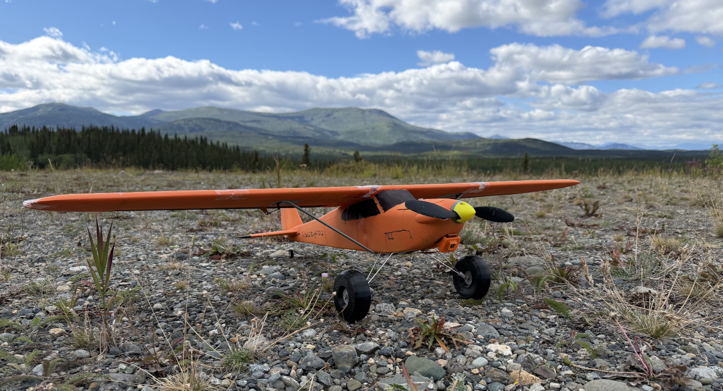
Eclipson Model B with Raspberry Pi Zero 2 W and Camera.
For the past couple of years, UAVs and drones have been on my mind, well, really just fixed-wing drones. So, in an effort to break away a bit from working on Dreamcast projects (still working on something cool right now but not ready to show yet), I wanted to spend some time working on remote control planes. I think the applications of UAVs is growing rapidly and up here in the North, in the middle of nowhere, even more-so.
A bit over a year ago, I had purchased the files and plans for a drone-style plane called the Flightory Stallion. It's a fairly involved and expensive build so, in the end, I never got further than ordering the necessary lightweight 3D printing filament and kind of shelved the project for later.
This spring though, my son got into planes and, what do you know, we had a 3D printer and filament ready-to-go. I wanted to scale things back though and try a simpler project. Partly to just take things slower instead of trying to jump straight into making an expensive drone, and partly so my son could help put things together and build some of the plane himself.
After a bit of research, and discussions with my son, we ended up purchasing plans for the Eclipson Model B. These plans also came with an exact parts list for the non-3D printed parts and recommendations for stuff like the transmitter/receiver combo which made ordering electronics pretty convenient.
So, with everything on the way, it was time to actually print the plane. It's printed almost entirely using lightweight PLA Aero filament, a special 3D printing filament that foams as it gets heated in the print nozzle. Because of the foaming, it is much less dense than standard PLA and ends up being about half the weight. It's also not nearly as durable as standard PLA, but I guess that's the tradeoff.
The way the parts are printed is also very clever. They're printed in 'spiral vase mode' which means one continuous extrusion of filament is laid down in a spiral so the nozzle never lifts off the part. This makes for a much smoother and nicer-looking part than traditional layer-by-layer printing, especially with lightweight PLA as it tends to foam and spew little bits of filament whenever the nozzle lifts off the part. Even the internal spars and strengthening is cleverly designed as sort of indents in the 3D model itself so that there is still some internal support without actually using infill from the slicer.
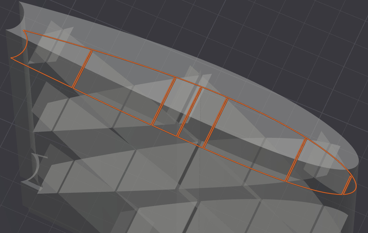
A single layer of a wing section being printed in vase mode. Internal supports are 'walls' baked into the 3D model itself.
Gluing all the printed pieces together was pretty satisfying as plane slowly took shape. This was also where my son got to have the most fun working on it. We probably went through half a bottle of super glue during the whole process.
As for the onboard electronics, it's extremely bare-bones with standard servos, an inexpensive 1250KV motor, speed controller, and a cheap receiver. After a bit of research, the one piece of electronics I added over the standard list was a gyroscope. Compared to fancy flight computers, the gyro is much simpler but, being a novice flyer, I wanted a bit of insurance.
Normally, the gyro just corrects sudden changes in the planes orientation but it can also be configured to always return the plane to level flight when no controller input is detected or limit how much the plane can roll or pitch. This ended up being a huge help and probably saved the plane in at least one instance.
Since this all started with an interest in drones and UAVS, and since the RC plane looks like, well, a plane, I wanted to make it a bit more 'drone-ish'. So, of course I have to strap a Raspberry Pi and camera to it. It was connected to the planes battery and was setup to both record to an SD card and stream it over wifi using itself as the access point.
Unfortunately, the whole camera setup was a complete failure for a couple of reasons. Firstly, it was positioned under the nose of the plane at a bit of a downward angle, hoping to maybe catch something interesting on the ground like a bear. However, being behind the propeller meant the video looked awful! This probably could have been avoided with some ground testing but I was eager to get out in the field. It's starting to make sense why so many drones use pusher props.
Even worse though, soon after takeoff the transmitter started alarming that it could not reach the receiver and cut out for several seconds. Thank goodness for the gyro, otherwise I'm sure the plane would have ended up in a tree. My theory is that the 2.4GHz of the Pi's wifi was interfering with the 2.4GHz of the transmitter, or possibly the Pi drawing too much power, as there were no more issues after removing the camera. For the interested viewer, feel free to check out the rather short flight video at the bottom of this post.
All-in-all, it was a fun project. I learned a lot about RC planes and UAVs, and got to spend some time with my son working on a project. And thankfully the plane did make several (mostly) successful landings, even if one was into a tree. I would love to spend more time on this stuff, long-range beyond visual line-of-sight would be really cool for surveying. Or maybe trying to recreate some of the gyros features using a Pi Pico would be fun.
Thanks for reading!