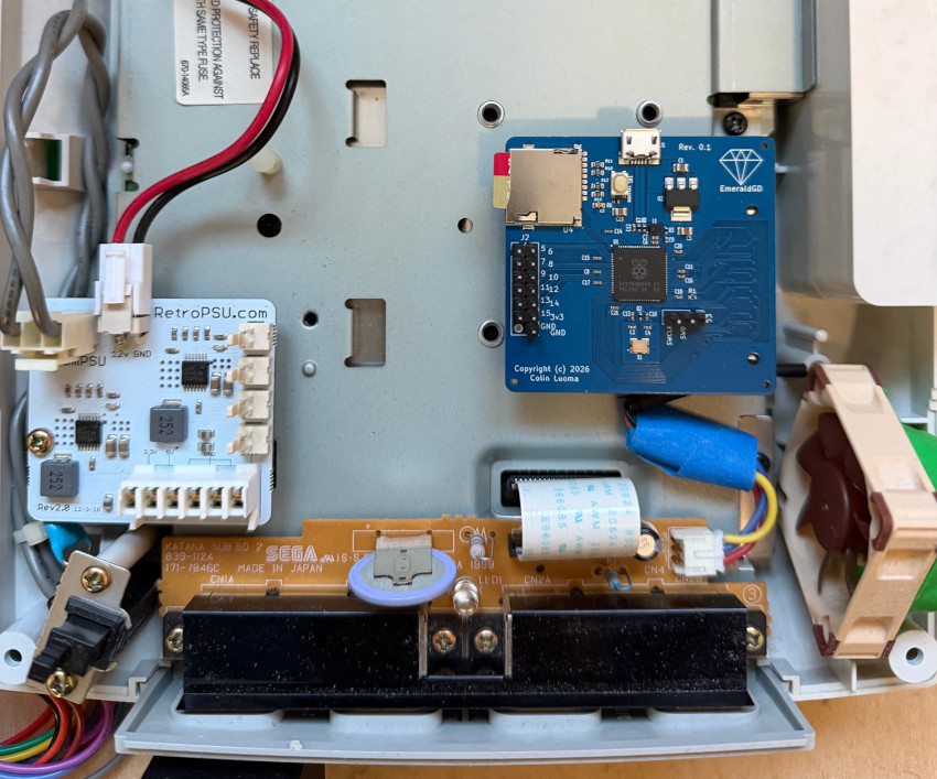
EmeraldGD prototype installed in a Dreamcast.
The PIO (programmable input/output) units on the RP2040 and RP2350 chips has been a game changer in a lot of applications. After getting familiar with using PIO to interface with the Dreamcast's controller port, I experimented talking directly to the console through its GD-ROM interface.
The idea came from hearing about another project, PicoIDE, an IDE emulator using the RP2350. I had also read that the Dreamcast interfaced with the GD-ROM via ATA, and so thought the RP2350 could probably be used here too.
So, for the past 6 months or so, I've been working on a Dreamcast ODE called EmeraldGD that uses essentially nothing but an RP2350 and an SD card. It can interface with the Dreamcast's normal ATA timings in both PIO and multiword-DMA, and supports CD-DA for game that use digital audio.
Even though the Dreamcast's GD-ROM connector is somewhat proprietary, it basically just brings the ATA and CD-DA (CD digital audio) interfaces together on one plug.
So, I harvested a GD-ROM connector from an old GDEMU board and built a little breakout board to collect traces from a GDEMU and to connect my RP2350 dev board to the Dreamcast. A cheap 16 channel 200MHz analyzer was just fast enough to capture ATA activity. 16 channels is not enough for the whole bus but it worked out all right since I usually only cared about a subset of the bus at any one time.
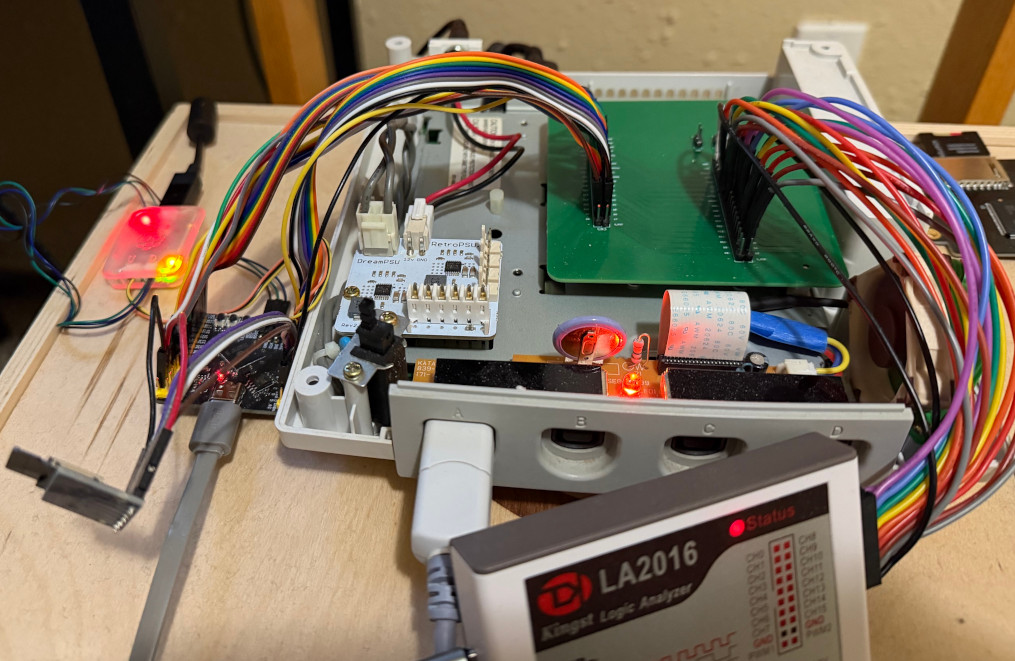
RP2350 dev board connected to a Dreamcast.
ATA
The Dreamcast uses standard parallel ATA to talk to the GD-ROM drive, which is quite an old standard by now. There's a lot of high-level descriptions of ATA online but finding really detailed stuff was weirdly difficult.
I did manage to find a nice document here that describes the ATA and ATAPI spec and was quite helpful to get a decent understanding. Claude (AI I know) was also really helpful in generating timing diagrams for different ATA operations. Comparing live traces to the documentation also helped a ton.
At a really high level, ATA is basically just a protocol for a host to read from and write to registers of a device. Several lines of the bus are used to setup a read or write, then the data lines get filled with required data. The data lines get sampled, and the whole process starts again.
For a read, when the Dreamcast pulls DIOR low, the drive needs to put the value of the requested register on the data lines as soon as it can. For a write, the Dreamcast pulls DIOW low then the drive just samples the data lines and writes that value into the chosen register.
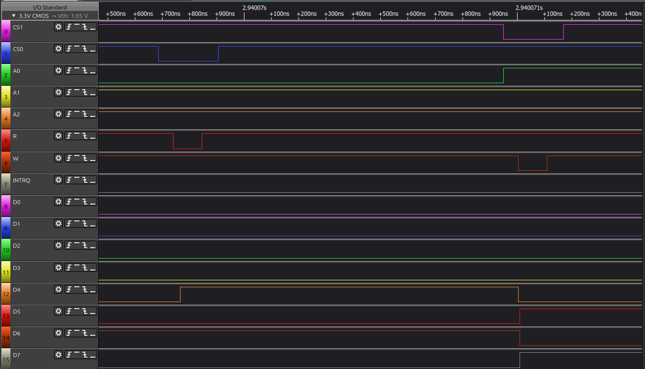
A sample ATA trace showing a register write, followed by a read.
The above trace (captured from a Dreamcast talking to EmeraldGD) shows two register operations: a read followed by a write, as indicated by first DIOR then DIOW going low.
The write in this trace is actually quite special, it is writing the value of 0xA0 to the Command register. This is part of the ATAPI interface and kicks off a Packet Command. When the drive receives this command code, it gets ready to receive a payload of data for a more complicated command like reading sector data from the disc, or getting the disc's table of contents.
On the Dreamcast, register reads and writes are typically 100ns. To put that into perspective, I set the clock speed of the RP2350 to around 200MHz, which means each clock is about 5ns, so there are only 20 clocks to get data on the lines. Way too fast to bitbang, but the RP's PIO hardware makes this possible.
Using PIO to Talk ATA
To be able to interface with the Dreamcast via ATA, the RP2350 needs to basically just do two things: sample data when a register write is given, and get the correct data on the data lines when a read is detected. Since it is the host that drives the read/write signal lines, these are the timing-critical pieces that the PIO blocks need to take care of.
Dealing with writes was pretty simple, I created a small program that just waits on the DIOW line to go low, then high, then sample the bus into a buffer. The CPU deals with writes on its own time. Pretty much every write I encountered from the Dreamcast was in preparation for a packet command, so as long as the write buffer is flushed before dealing with any commands, everything seemed to work well.
Read requests were the much trickier task. There's absolutely no way that a PIO program would be able to get data from the CPU within the 100ns window, remember that's only 20 clock cycles! The solution I found was to use a new feature of the RP2350 chip that allows it to access arbitrary entries in its RX FIFO.
Each PIO state machine has 4 32-bit entries in its RX FIFO (enough for 8 16-bit registers) which are usually used for sampling data, but it's also possible to use them in a sort of 'register' mode where the 4 entries can be accessed arbitrarily via the mov instruction.
So, I get the address of the requested register from the address lines, then grab it from the RX FIFO using: mov osr rxfifo[y]. I still update the registers on the CPU side, but the PIO program can always respond to reads without needed to go to the CPU.
In addition to register access there are also two ways to transfer larger chunks of data from the drive to the Dreamcast. The more basic method is called PIO (unfortunately named the same as PIO on the RP chips). PIO transfers data via standard ATA register reads through the Data register. Basically, the console just reads the Data register a bunch of times until it has all the data it's expecting.
The way I handle this is with a separate PIO program (the RP's PIO this time) that is triggered with an interrupt when the Data register is read. This program is fed with the data from the CPU via the RP's DMA feature so it can push out 16-bits of new data every time the Data register is read.
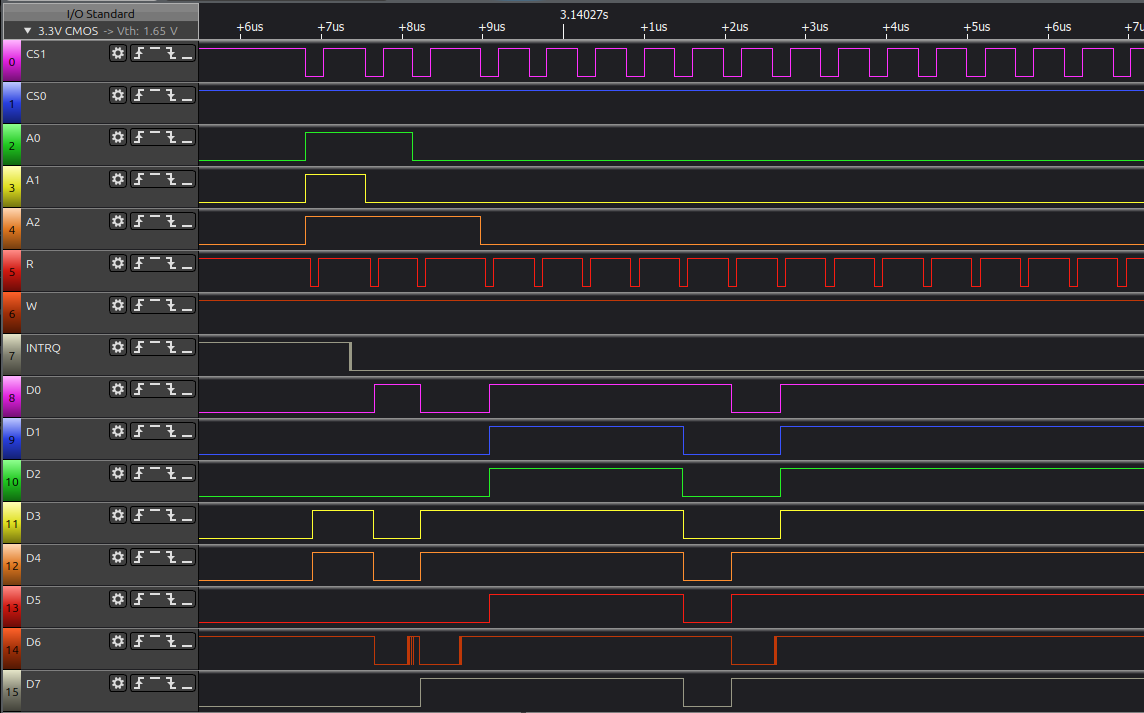
A sample ATA trace showing a PIO data transfer from RP2350.
The above trace shows the start of a PIO data transfer, with the response data being supplied from the RP2350. A full Data register read cycle takes about 600ns, a theoretical limit of 3.3MB/s, pretty slow.
Another method of transferring data is called DMA (again an unfortunate name clash). Instead of reading data through the Data register, the Dreamcast and the drive do a bit of a handshake using some special-purpose DMA lines, then the Dreamcast just strobes the DIOR line continuously until it gets all the data it wants. This is much faster than PIO data transfers because it skips the whole setup for requesting a specific register.
This is was actually pretty easy to create a PIO program for. I feed a state machine with data using the RP's DMA feature and the state machine will just continuously pump out 16-bits of data from the buffer every time the Dreamcast strobes DIOR while in the DMA state.
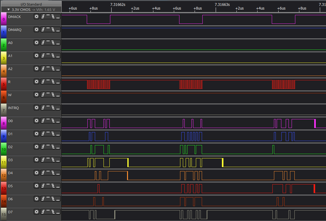
A sample ATA trace showing a DMA data transfer from RP2350.
The above trace shows a DMA data transfer, with the response data being supplied from the RP2350. There's no register reads here, just the Dreamcast bringing DMACK (DMA acknowledge) low then strobing the read line. A single read cycle is about 140ns, a theoretical limit of about 14MB/s, or about 4 times faster than a PIO data transfer.
Most Dreamcast games that I tested tend to use DMA more than PIO, especially for really large data transfers. But, homebrew games using KallistiOS, I noticed tend to use PIO more frequently.
The ATA interface is also only one piece of the whole project, but it was the most interesting for me to work through, so I thought it was worth talking about here. There's lots more like: parsing disc image formats, dealing with different ATAPI packet commands, and of course CD-DA which is important for a lot of games. Maybe I will expand on some of that stuff in another blog post.
Compared to working with the Maple bus, the G1/ATA bus was much more forgiving. As long as the timings for register accesses are kept to, the Dreamcast will just kind of dutifully wait for a response to whatever it asked for, or whatever you tell it to expect. So, while it's certainly more complicated than the Maple bus, at least on the wire, but at the same time was a lot more straightforward to deal with in other ways.
Building a Prototype
Along with the firmware, I also designed a prototype board for use on a real Dreamcast. It's mostly using the RP2350 reference design as a base and just wiring up the GPIO to the GD-ROM connector. I'd never designed a board using a bare RP chip before so it was a fun experience. Those GD-ROM connectors also seem to be very hard to find and I ended up harvesting one from another GDEMU clone.
I went with the RP2354B chip because it has 2MB of built-in flash storage so is a bit cheaper than using an external flash chip, and keeps the board a bit smaller. The unused GPIO are also broken out just in case.
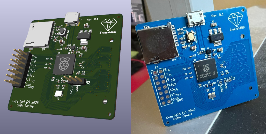
KiCAD render and prototype board.
Surprisingly (or not maybe? I just always expect the worst from my PCB designs) the PCBs came back working without any issues that I could see.
I tried to make it compatible with the latest version of OpenMenu. OpenMenu and GD MENU Card Manager are very convenient and do a lot of the heavy lifting for managing lists of games so it's nice to support it.
Now that I have an interface to the Dreamcast through the G1 bus, I was thinking about what else could be done with it. One idea was OpenMenu's settings and Serial VMU features. There's no technical reason that that stuff couldn't be saved on EmeraldGD using a custom command packet. I think it would be super cool to leverage the serial VMU onto the G1 bus instead, to essentially get unlimited VMU saves without any additional hardware.
Thanks for reading!