Author

Colin is a data analyst, currently working in Whitehorse, Yukon.

Showing blog posts written by: Colin Luoma

Using the Steam Controller on the Sega Dreamcast with Raspberry Pi Pico 2

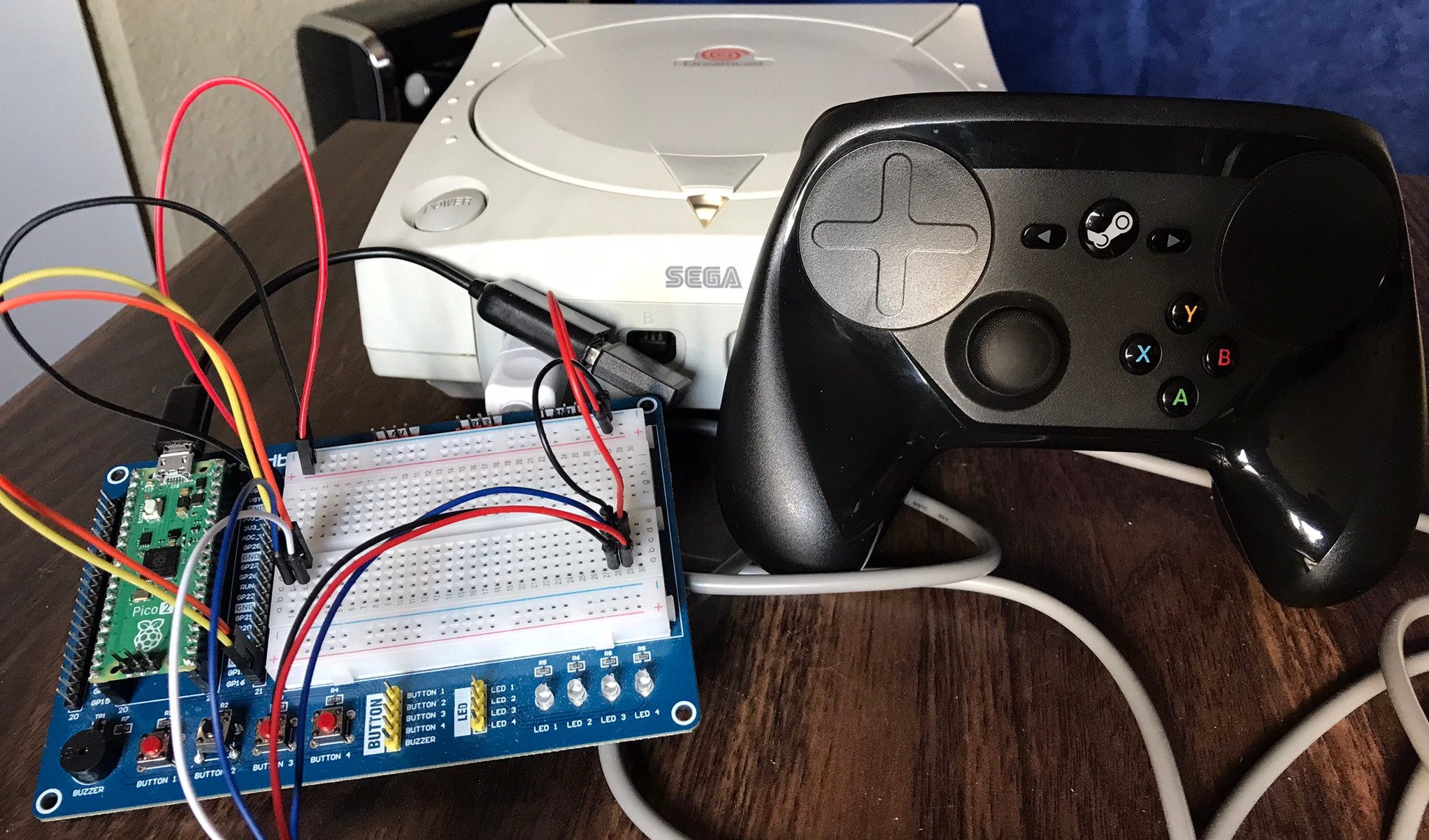
Pi Pico 2 with Steam Controller and dongle next to a Dreamcast.

I've been scratching my head to come up with a project to play around with the Raspberry Pi Pico's PIO (programmable input/output) and eventually had the idea for some sort of converter to use non-Dreamcast peripherals on the Dreamcast. Of course, all good ideas have already been done, in this case not once or twice, but three times as far as I'm aware, and probably more.

All of these projects are based on the RP2040 chip (original Pico), while I wanted to make use of the new RP2350 (Pico 2) chip. In particular, there is a new PIO input masking feature available on the RP2350 which I think makes for a better implementation for reading the Dreamcast's Maple bus. Also, none of the previously-listed projects actually allow me to use by beloved Steam Controller. All this to say that I really wanted to try things on my own.

The Maple Bus

The Maple bus is how the Sega Dreamcast talks to peripherals on the controller port. It's a two-wire protocol where each wire takes turns being the clock and being the data. Essentially when a wire goes low, it signals that there is data on the other wire (a 1 or a 0), it allows a bit of time to read the bit, before the appropriate wire goes high in preparation for another falling edge.

Below is a sample reading of the Dreamcast send a packet to a controller. In this particular case it's Command 0x01 which is a request for information about what the peripheral is capable of. Hopefully you can see that every falling edge represents one bit of data, read from the other wire. I hope to go into more detail about the Maple protocol in a separate blog post.

PulseView reading of the Dreamcast sending a Maple packet.

Reading and Writing with Maple

To actually read and write data to the Maple bus, the RP2350's programmable input/output (PIO) sounded like the perfect solution. PIO on the RP chips are like little tiny co-processors that can run at a fixed clock rate. Each PIO block has 4 state machines, each with a few registers, and access to a shared space of up-to 32 instructions from a very limited set of instructions.

Both the reading and writing PIO programs got close to the 32 instruction limit so I ended up using two of the three PIO blocks available on the RP2350. With four state machines in each PIO block, it should - in theory - be possible to read and write from up to four controller ports on the Dreamcast. Though I'm only using one at the moment.

To read the Maple bus, I wrote a PIO program that constantly checks the value of the 2 data lines, waiting for the value to change due to a line going high or low. It takes advantage of the fact that the Maple bus only has data available during a falling edge, meaning a valid is read when the voltage on the wires either goes 11->10/01 or 10/01->00. The former is interpreted as a 1 and the latter as a 0. The PIO program then pushes this bit (eventually) back to the main C program where it can be interpreted.

Writing to the Maple bus was a lot more straightforward. A bunch of data is fed to the PIO which clocks out the start-of-packet signal then starts sending the data accordingly, before finishing with the end-of-packet signal when no more data is available in its buffer.

The whole thing ends up looking like this, on the wire, where the first packet is a request for data coming from the Dreamcast, and the second packet is the requested data being supplied by the Raspberry Pi:

PulseView reading of the Dreamcast sending a Maple packet requesting data from the controller.

The above packet is send by the Dreamcast and has a command code of 0x9, which is a 'Get Condition' command. It also has some included data (the pink bubbles) with a value of 0x00000001 which should be interpreted as 'Controller'. So, it's asking for the current status of the controller.

PulseView reading of the Pico responding to the Dreamcast with data.

This packet is sent by the Pico in response to the Get Condition command. It has a command code of 0x8 which says that this is a response packet with some data attached. The first 4 bytes are again 0x00000001 saying this is about the controller, then the remaining bytes describe which buttons are pressed and the current axis values of the joystick and triggers.

The whole request and response only takes about 125 microseconds or 0.125 milliseconds. But the controller state is requested about every 16.7 milliseconds, or once per frame at 60fps.

Getting Data from the Steam Controller

Getting USB data from the Steam Controller was surprisingly straightforward since the Pico SDK has TinyUSB as a built-in library. So, with that and the hid-controller example from the TinyUSB docs I was able to start getting the raw USB data quite quickly.

To interpret the raw data that was coming from the controller, I referenced Linux's hid-steam driver as it has mappings as to the meaning of specific bits and bytes sent by the Steam Controller.

Then it was just a matter of keeping track of what buttons are pressed, and sending that data to the Dreamcast via the Maple bus whenever it was requested.

Closing

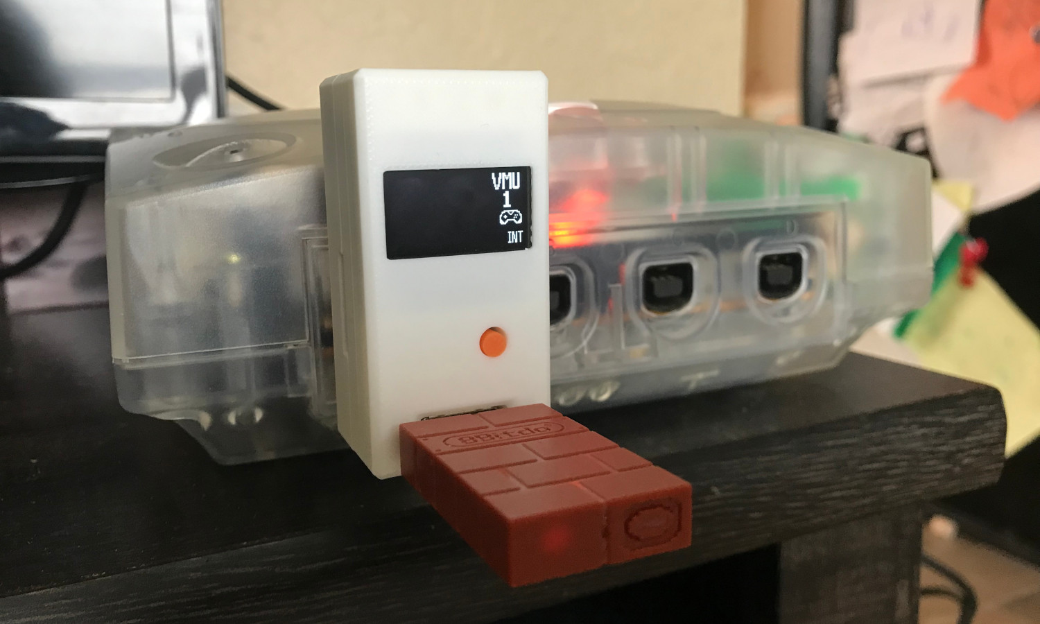
If you own a Steam Controller, and would like to try this out for yourself, I've written a short visual guide in a previous blog post. It would be great to get feedback as I hope to built this into a standalone device with support for more kinds of controllers.

This really wouldn't have been possible without the awesome Dreamcast documentation from Marcus Comstedt. I'm no electrical engineer so his explanations of the exact workings of the Maple bus were invaluable. He also happened to write the Maple bus decoder for PulseView which generates the nice little data bubbles under the logic analyzer readouts. This project would have easily taken twice as long without that. I highly recommend checking out his stuff if you are interested in knowing more about the inner workings of the Sega Dreamcast.

There's also a little video showing the controller in action below, playing some Sonic Adventure.


Tags:


How To: Use a Steam Controller on the Sega Dreamcast

Required Hardware

  • Raspberry Pi Pico 2
  • Micro-USB to female USB-A adapter
  • A Dreamcast controller cable
  • Steam Controller with USB dongle

Controls

Controls are mapped as you would expect. The exception is the left touchpad of the Steam Controller which must be clicked to be read as DPad input on the Dreamcast.

Download

Download the pico2maple uf2 firmware file.

Holding down the BOOTSEL button while connecting the Pico to a PC should make it appear as a USB storage device. Then simply copy the pico2maple uf2 file over and the Pico should reboot itself with the new firmware.

Construction

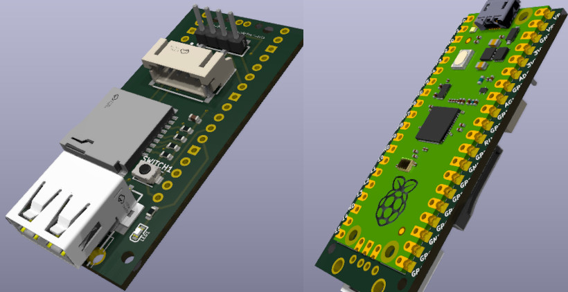
Use a multi-meter to check which wires on the controller cable correspond to the following pins on the controller plug.

Connect the wires to the labelled pins on the Pico below by soldering or otherwise.

With everything wired up, it's simply a matter of plugging in the Steam Controller dongle to the Pico using the USB-A to Mini-USB adapter and plugging the controller cable into the Dreamcast.

Once the Dreamcast is powered on, power on the Steam Controller and it should connect and be a usable Dreamcast controller!


Tags:


Feedback Kiosk Using Raspberry Pi Pico W

Have you ever seen those kiosks at airports with smiley-faces on them? As you walk by, you hit a big button to express how you feel at the time. Well I was looking for a reason to play around with the Raspberry Pi Pico W, and thought that trying to recreate my own version of one of these would be a fun project.

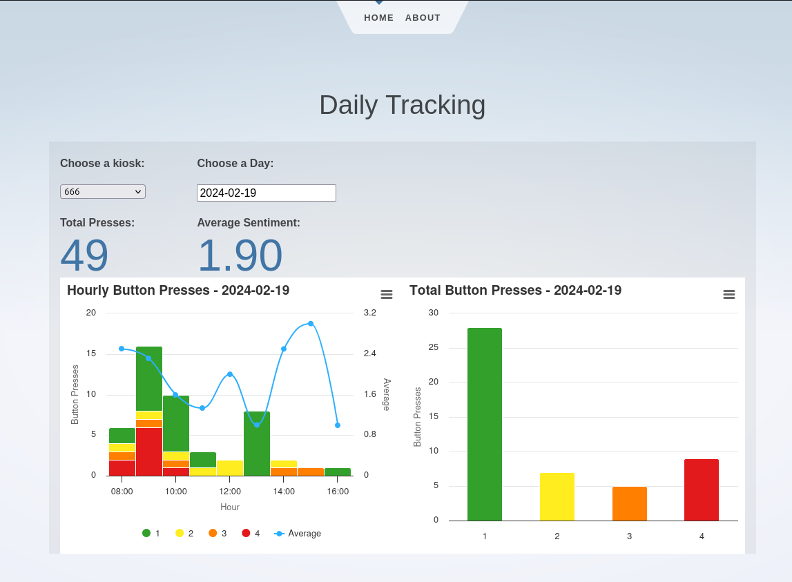
The whole system is split into two parts: the physical kiosk, and the server backend/frontend. The physical kiosk connects to WiFi, logging all button presses both locally and sending them to the server backend. There's also a nice little web frontend to see some daily statistics on which buttons are being pressed.

The Kiosk

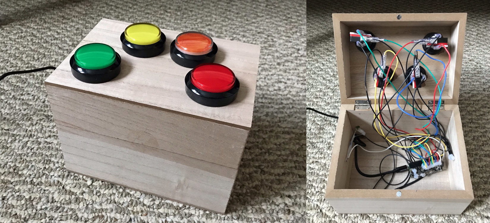
The Feedback Kiosk box and its internal wiring.

The brains, and main component, of the kiosk is a Raspberry Pi Pico W. To get all the features I wanted though, I also included the Adafruit Adalogger which is a combination real-time clock and SD card adapter for the Pico. It's essentially built for logging data with timestamps, exactly what is needed for the kiosk. Aside from those two pieces, I also picked up a few large push buttons off Amazon and a small wooden enclosure from Walmart. I think the push buttons are targeted at people wanting to make their own Pop'n Music controller, but they worked well for this project.

The basic operation of the kiosk is pretty straightforward. It constantly waits for button presses and when it detects a press, it logs it locally to the SD card and, using WiFi, sends it to the server for safer keeping. One of the cool features of the Pico is that it is multi-core. So, one core can constantly check for button presses while the other can handle the logging and HTTP requests. This has the advantage of the main loop never getting blocked by slow WiFi and we never miss a button press.

Another interesting feature I built into the kiosk is a simple webserver that allow users to change the WiFi connection settings. If the kiosk can't connect to a WiFi hotspot, it starts itself as its own access point. Connecting to this access point from a smartphone takes the user to a simple webpage where they can supply connection details to connect to another access point. Pretty handy when moving it between different locations.

Alternatively, the kiosk can also be started in offline mode by holding down the red button on boot. This will only log data to the SD card and not try to use any wireless features.

The Server

Screenshot of the Svelte webpage to view daily button presses.

For the server backend, I wanted to try programming something new and decided to write it in Rust using the Actix web framework. I don't think this project was large enough to get a good grasp on Rust, but it was a nice learning experience for sure. Otherwise, I would normally have used C and my own http lib, bittyhttp, for a small project like this.

One thing I liked with Rust was its great package manager and compiler. It made it very easy to get whatever libraries I needed and statically cross-compile the whole application into a single executable. Then I could simply copy it over to the server actually running it. I know this is possible with other languages as well but Rust's package manager and compiler just made it so easy I really appreciated that.

Currently, there are only a few endpoints built into the backend: one to receive button presses, one to send back button press data (for the frontend), and another to send the current time information to the kiosk, which is handy for setting the RTC.

As for the frontend, I stuck with Svelte, which I have use for several projects in the past. For simple situations like this, I find that it makes things very quick and easy to get the behaviour that I want. My favorite feature of Svelte though is the ability to compile everything to static pages, meaning I don't need any other server components aside from the Rust backend.

Closing

Although this whole thing is very much a prototype, I think it would be really fun to deploy the feedback kiosk somewhere that is busy enough to get a lot of data. I'd really like to see how people's mood changes throughout the day, or even throughout a week.

Code for this project is also available on GitHub: https://github.com/cluoma/big_button

Thanks for reading!


Tags:


Detecting Northern Lights using Raspberry Pi and Convolutional Neural Network - Part 1

Pi Camera and a Northern Lights image with prediction.

At the moment, I'm fortunate to live in a part of the world where visible Northern Lights are fairly common. The problem is though, they may only show up for a few minutes during the night so you have to either be a real night-owl or get lucky. I wanted to build something to help me catch the Northern Lights more often.

The idea mostly came after seeing the recent release of the Raspberry Pi camera module 3 and wanting an excuse to do something with it.

In this blog post I'll go over the proof of concept of the idea and how I hope to develop the project into something a little nicer.

I already had a bit of a head-start on the some of the infrastructure from a previous project of mine, a Raspberry Pi baby monitor. It's a two-part setup a camera-equipped Pi Zero W and a separate server component running on my home server. The Pi Zero is a 'dumb' piece that only takes pictures every few seconds and sends it via http, while all the business logic of collecting, storing, and displaying pictures sits on my server. This makes it easy to unplug and move the camera around without causing too much trouble to the whole system's operation.

For this particular project, my Pi Zero got a camera 3 upgrade and was pointed straight at the sky out my north-facing, upstairs window. It captures a picture every 5 seconds and sends it to my home server where it's stored for later; most nights capturing about 7000 images. Each image is stored in a folder and metadata about the image is written to a small sqlite3 database. To label the images, I was able to use my computer's image previewer to quickly scrub through a nights worth of images and mark them in the database as either containing Northern Lights or not. It only took about 30 minutes per night but it was pretty boring work none-the-less.

With labelled images, I could sort them into a proper training dataset of 'aurora' and 'sky' pictures. I then trained a large convolutional neural network built using the Keras Python package to classify the pictures. The Keras documentation has a nice article called 'Image Classification from Scratch' which was a good starting point for this task. It shows how to build a model to classify pictures as either dogs or cats, so it was fairly straightforward to adapt it to the task of classifying 'Aurora' or 'No Aurora'.

Below is a YouTube video showing a full night of particularly active Northern Lights. The 3rd number in the top-left of each image is the prediction from the trained neural network, the closer to 1 the number is the more confident the model is that the picture contains Northern Lights. None of the pictures in this timelapse were used in training the model. Skip ahead to 0:50 to see the Northern Lights in action!


With the concept proven, I'd like to build the whole project out a little bit more. The step 2 is to build a proper webapp that can receive pictures from the Pi, classify them, and display them. The best pictures (according the model) will get saved, and on really good nights it should send me a text message or some other notification. It will probably be a bit tricky to come up with a good heuristic for this, as sometimes Northern Lights will be gone within a few minutes.

Step 3 is to build a better enclosure for the Raspberry Pi so that I can move it outside to a more permanent location. I'm more of a software person so I haven't thought too much about this. If anybody has any god suggestions please let me know.

That's it for now. Thanks for reading. I'll try to put the code and training pictures on GitHub soon.

Update

I've been playing a bit with Google Colab and thought it would be a good way to share the training code and data for this project.

Python Notebook: https://colab.research.google.com/drive/1CFNfKZH_WyrGN71t4Jx4NU-FzBTAeZP5?usp=sharing

Training Images (1.4GB): https://drive.google.com/file/d/1N8uuIMo6AzM6SGoTBQh7iWK_SGIOyh6n/view?usp=sharing


Tags:


Interactive Digit Classification Using Neural Network Trained on MNIST Data

Several years ago, I created a fully connected neural network from scratch in C as a learning exercise. I followed the first few chapters of Michael Nielson's book 'Neural Networks and Deep Learning' that I highly recommend.

The network was designed to train on the MNIST number dataset, which is a well-known dataset used in many machine learning examples. The goal is to identify hand-written digits as any number between 0 and 9. The final network performed quite well and achieved 97.14% accuracy on the test dataset. Not bad for a bit of matrix algebra wrapped up in some C code.

Anyways, ever since then I've had the idea to create a little browser widget to let people use the model I trained in an interactive way. Of course, I was beaten to the punch once, twice, and many more times I'm sure. But even still I wanted to see how well my model would perform at this task.

Homemode Fully Connected Neural Network

Before starting to work on the widget, I beefed up my neural network a little bit and was able to train one with a 98.2% accuracy on the test MNIST data. I then used a web framework called Svelte to create a drawing and predicting widget. Since my model is all simple linear algebra, exporting the weights from C and hard-coding them into Javascript was not too much work. Libraries like Math.js made it pretty easy to recreate everything. The final product is the widget you see below. It runs entirely client side in the browser using my trained neural network.

* does not run on iOS Safari, possible macOS Safari as well *

If you tried a few numbers, you probably noticed that the predictions can often be rather poor. I found that it has a really difficult time with '1's , '0's, and '9's. It was a bit disappointing, even with a 98.2% accuracy on test data, it still has a lot of trouble with new numbers. My guess is that, due to the fully-connectedness of the network, it has a difficult time generalizing new data. Like, if a '1' is off to the side or at a wrong angle that isn't present in the training data then it will predict incorrectly.

Keras/Tensorflow Convolutional Neural Network

Another type of network often used on the MNIST data is a convolutional network. I won't go into the topic here but this explanation was pretty helpful for my understanding. Convolutional networks work so well on MNIST that it's actually one of the 'getting started' examples for Keras.

I wanted to see how much the widget would improve with a convolutional network instead of my fully-connected version. So, I followed the Keras example and trained one in Python that reached an accuracy of 99.3% on the test data. Crucially though, I believe that it generalizes much better and is therefore more tolerant to digits that may not be presented in exactly the same way as in the training data. And the results definitely show, in my testing it seems to predict the correct digit much more often then my homemade model.

Again, the widget below is running entirely in the browser using the the Tensorflow.js library. Tenforflow.js allowed me to export the model from Python and import it directly into the Svelte widget.

* does not run on iOS Safari, possible macOS Safari as well *

Embedding Widgets

Because the widgets run entirely client-side, feel free to embed them anywhere on your own site using the code snippets below. They are web components that use a shadow DOM so should always look the same no matter where they are embedded. Kind of like frame, but for the modern age.

<script src="https://www.cluoma.com/js/mnist_widget.js"></script>
<div><mnist-checker-widget /></div>
<script src="https://www.cluoma.com/js/mnist_convolution_widget.js"></script>
<div><mnist-convolution-checker-widget /></div>

Full source code for this project is posted on my GitHub.


Tags: